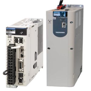
Açıklama
Teknik Özellikler
| Ürün serisi | Altivar 32 |
|---|---|
| Ürün ya da bileşen tipi | Değişken hızlı sürücü |
| ürün varış yeri | Senkron motorlar Asenkron motorlar |
| ürüne özel uygulama | Yüksek güçlü makineler |
| kullanılabilir işlev | – |
| montaj stili | Soğutma bloklu |
| bileşen adı | ATV32 |
| EMC filtresi | Sınıf C2 EMC filtresi entegre |
| fazların ağ sayısı | 3 faz |
| [Us] nominal besleme gerilimi | 380…500 V % – 15…10 |
| besleme gerilimi limitleri | 323…550 V |
| besleme frekansı | 50…60 Hz – 5…5 % |
| Şebeke frekansı | 47,5…63 Hz |
| motor gücü kW | 2,2 kW -de 380…480 V |
| motor gücü hp | 3 hp -de 380…480 V |
| hat akımı | 6,6 A için 500 V 3 faz 2,2 kW / 3 hp 8,7 A için 380 V 3 faz 2,2 kW / 3 hp |
|---|---|
| görünen güç | 5,7 kVA -de 500 V 3 faz 2,2 kW / 3 hp |
| muhtemel hat Isc | 5 kA için 3 faz |
| nominal çıkış akımı | 5,5 A -de 4 kHz 500 V 2,2 kW / 3 hp |
| maksimum geçici akım | 8,3 A için 60 s 2,2 kW / 3 hp |
| çıkış frekansı | 0,0005…0,599 kHz |
| nominal anahtarlama frekansı | 4 kHz |
| anahtarlama frekansı | 2…16 kHz ayarlanabilir |
| hız aralığı | 1…100 için asenkron motor açık döngü modunda |
| hız doğruluğu | Nominal kaymanın +/- % 10’u 0,2 Tn – Tn |
| tork doğruluğu | +/- 15 % |
| geçici aşırı moment | 170…200 % |
| frenleme torku | <= % 170 frenleme direnci ile |
| asenkron motor kontrol profili | Gerilim/frekans oranı – Enerji Tasarrufu, karesel U/f Sensörsüz akı vektör kontrolü, standart Gerilim/frekans oranı, 5 nokta Sensörsüz akı vektör kontrolü – Enerji Tasarrufu, NoLoad yasası Gerilim/frekans oranı, 2 nokta |
| senkron motor kontrol profili | Sensörsüz vektör kontrolü |
| düzenleme döngüsü | Ayarlanabilir PID regülatör |
| motor kayma kompanzasyonu | Ayarlanabilir % 0…300 Gerilim/frekans oranında (2 veya 5 puan) geçerli değil Otomatik her türlü yük |
| yerel sinyalleme | 1 LED kırmızı için sürücü gerilimi 1 LED yeşil için CANopen çalışması 1 LED kırmızı için CANopen hatası 1 LED kırmızı için sürücü hatası |
| çıkış gerilimi | <= güç besleme gerilimi |
| gürültü seviyesi | 43 dB ‘e uygun86/188/EEC |
| yalıtım | Güç ve kontrol arasındaki elektrik |
| elektrikli bağlantı | Vidalı terminal, kelepçeleme kapasitesi: 0,5…1,5 mm², AWG 18…AWG 14 (kontrol) Çıkarılabilir vidalı terminaller, kelepçeleme kapasitesi: 1,5…2,5 mm², AWG 14…AWG 12 (motor/frenleme direnci) Vidalı terminal, kelepçeleme kapasitesi: 1,5…4 mm², AWG 14…AWG 10 (güç besleme) |
| sıkma torku | 0,5 N.m, 4,4 lb/ft (kontrol) 0,7 N.m, 7,1 lb/ft (motor/frenleme direnci) 0,6 N.m, 5,3 lb/ft (güç besleme) |
| besleme | Referans potansiyometre için dahili besleme (1 – 10 kOhm): 10,5 V DC +/- 5 %, <10 mA, koruma tipi: aşırı yük ve kısa devre koruması |
| analog giriş sayısı | 3 |
| analog giriş tipi | AI1 gerilim: 0…10 V DC, empedans: 30000 Ohm, çözünürlük 10 bit AI2 çift kutuplu diferansiyel gerilim: +/- 10 V DC, empedans: 30000 Ohm, çözünürlük 10 bit AI3 akım: 0…20 mA (veya 4-20 mA, x-20 mA, 20-x mA veya yapılandırmy göre diğer modeller), empedans: 250 Ohm, çözünürlük 10 bit |
| örnekleme süresi | 2 ms (AI1, AI2, AI3) – analog girisler 2 ms (AO1) – analog girisler |
| yanıt süresi | LI1…LI6 8 ms, tolerans +/- 0,7 msn için lojik çikislar R1A, R1B, R1C 2 ms için röle çikislar R2A, R2C 2 ms için röle çikislar |
| doğruluk | +/- % 0,2 (AI1, AI2, AI3) -10…60 °C sıcaklık için +/- % 0,5 (AI1, AI2, AI3) 25 °C sıcaklık için +/- 1 % (AO1) 25 °C sıcaklık için +/- % 2 (AO1) -10…60 °C sıcaklık için |
| doğrusallık hatası | Maksimum değerin +/- % 0,2…0,5’i (AI1, AI2, AI3) +/- % 0,3 (AO1) |
| analog çıkış sayısı | 1 |
| analog çıkış tipi | AO1 yazılım-yapılandırılabilir akım 0…20 mA, empedans: 800 Ohm, çözünürlük 10 bit AO1 yazılım-yapılandırılabilir gerilim 0…10 V, empedans: 470 Ohm, çözünürlük 10 bit |
| Dijital çıkış sayısı | 3 |
| Dijital çıkış tipi | Yapılandırılabilir röle lojiki: (R1A, R1B, R1C) NA/NK – 100000 cycles Yapılandırılabilir röle lojiki: (R2A, R2B) NA – 100000 cycles Lojik: (LO) |
| minimum anahtarlama akımı | 5 mA -de 24 V DC için yapılandırılabilir röle lojiki |
| maksimum anahtarlama akımı | R1: 3 A -de 250 V AC dirençli yük, cos phi = 1 R1: 4 A -de 30 V DC dirençli yük, cos phi = 1 R1, R2: 2 A -de 250 V AC endüktif yük, cos phi = 0,4 R1, R2: 2 A -de 30 V DC endüktif yük, cos phi = 0,4 R2: 5 A -de 250 V AC dirençli yük, cos phi = 1 R2: 5 A -de 30 V DC dirençli yük, cos phi = 1 |
| Dijital giriş sayısı | 7 |
| Dijital giriş tipi | Programlanabilir (blok/kaynak) (LI1…LI4)24…30 V DC, ile seviye 1 PLC Darbe girişi 20 kpps olarak programlanabilir (LI5)24…30 V DC, ile seviye 1 PLC Anahtar-yapılandırılabilir PTC prob (LI6)24…30 V DC Güvenli tork kapatma (STO)24…30 V DC – 1500 Ohm |
| Dijital giriş lojiği | Negatif lojik (blok) (LI1…LI6), > 19 V (durum 0), < 13 V (durum 1) Pozitif lojik (kaynak) (LI1…LI6), < 5 V (durum 0), > 11 V (durum 1) |
| hızlanma ve yavaşlama rampaları | S CUS Lineer Yavaşlama rampasının adaptasyonu Rampa anahtarlama Yavaşla rampasının otomatik durdurma DC enjeksiyonu U |
| durana kadar frenleme | DC enjeksiyon ile |
| koruma tipi | Giriş faz kesmeleri: sürücü Çıkış fazları ve toprak arasındaki aşırı akım: sürücü Aşırı ısınmaya karşı koruma: sürücü Motor fazları arasındaki kısa devre: sürücü Termal koruma: sürücü |
| haberleşme port protokolü | Modbus CANopen |
| konnektörün tipi | 1 RJ45 (ön yüzde) için Modbus/CANopen |
| fiziksel arayüz | 2 telli RS 485 için Modbus |
| iletim çerçevesi | RTU için Modbus |
| polarizasyon tipi | Empedans yok için Modbus |
| adreslerin sayısı | 1…127 için CANopen 1…247 için Modbus |
| erişim yöntemi | Slave CANopen |
| elektromanyetik uyumluluk | 1,2/50 µs – 8/20 µs kesinti bağışıklık testi, seviye 3 ‘e uygunIEC 61000-4-5 Iletimli radyo frekansı bağışıklık testi, seviye 3 ‘e uygunIEC 61000-4-6 Elektrik hızlı geçici/patlama bağışıklık testi, seviye 4 ‘e uygunIEC 61000-4-4 Elektrostatik deşarj bağışıklık testi, seviye 3 ‘e uygunIEC 61000-4-2 Yayılmalı, radyo frekansı elektromanyetik alan bağışıklık testi, seviye 3 ‘e uygunIEC 61000-4-3 Gerilim düşüşleri ve kesintileri bağışıklık testi ‘e uygunIEC 61000-4-11 |
| Genişlik | 60 mm |
| Yükseklik | 325 mm |
| Derinlik | 245 mm |
| Ürün ağırlığı | 3 kg |
| seçenek kartı | Haberleşme kartı için CANopen daisy zinciri Haberleşme kartı için CANopen açık stil Haberleşme kartı için DeviceNet Haberleşme kartı için Ethernet/IP Haberleşme kartı için Profibus DP V1 |
| işlevsellik | Orta |
| özel uygulama | Diğer uygulamalar |
| Standartlar | EN 55011 sınıf A grup 1 EN/IEC 61800-3 EN 61800-3 ortam 1 kategori C2 EN/IEC 61800-5-1 EN 61800-3 ortam 2 kategori C2 |
|---|---|
| Ürün sertifikaları | UL CSA GOST NOM 117 C-Tick |
| İşaretleme | CE |
| kirletme derecesi | 2 ‘e uygunEN/IEC 61800-5-1 |
| IP koruma derecesi | IP20 ‘e uygunEN/IEC 61800-5-1 |
| titreşim direnci | 1 gn[Alan](f =[Alan]13…200 Hz) ‘e uygunEN/IEC 60068-2-6 1,5 mm tepeden tepeye[Alan](f =[Alan]3…13 Hz) ‘e uygunEN/IEC 60068-2-6 |
| darbe dayanımı | 15 gn için 11 ms ‘e uygunEN/IEC 60068-2-27 |
| bağıl nem | 5…95 % yoğuşmasız ‘e uygunIEC 60068-2-3 5…95 % damlayan su olmadan ‘e uygunIEC 60068-2-3 |
| çalışma için ortam hava sıcaklığı | -10…50 °C olmadan 50…60 °C değer kaybı faktörü ile |
| Depolama ortam koşulları | -25…70 °C |
| çalışma yüksekliği | <= 1000 m olmadan 1000…3000 m 100 m başına % 1 akım düşüşüyle |
| Çalışma konumu | Dikey +/- 10 derece |
| Garanti | 18 months |
|---|
Dimensions Drawings

Mounting and Clearance

The drive is prepared to be equipped with an optional GV2 circuit-breaker.
The GV2 circuit-breaker is directly mounted on the drive. Mechanical and electrical link are made using the optional adapter. The options are supplied with detailed mounting instruction sheet.
NOTE: The product overall dimension, including GV2 adapter and EMC plate mounted, becomes 424 mm (16.7 in.)

Connections and Schema
Connection diagrams conforming to standards EN 954-1 category 1 and IEC/EN 61508 capacity SIL1, stopping category 0 in accordance with standard IEC/EN 60204-1.

Connection diagrams conforming to standards EN 954-1 category 1 and IEC/EN 61508 capacity SIL1, stopping category 0 in accordance with standard IEC/EN 60204-1.

Connection diagrams conforming to standards EN 954-1 category 3 and IEC/EN 61508 capacity SIL2, stopping category 0 in accordance with standard IEC/EN 60204-1.
When the emergency stop is activated, the drive power supply is cut immediately and the motor stops in freewheel, according to category 0 of standard IEC/EN 60204-1.
A contact on the Preventa XPS AC module must be inserted in the brake control circuit to engage it safely when the STO (Safe Torque Off) safety function is activated.

The STO safety function integrated into the product can be used to implement an “EMERGENCY STOP” (IEC 60204-1) for category 0 stops.
With an additional, approved EMERGENCY STOP module, it is also possible to implement category 1 stops.
STO function
The STO safety function is triggered via 2 redundant inputs. The circuits of the two inputs must be separate so that there are always two channels. The switching process must be simultaneous for both inputs (offset < 1 s).
The power stage is disabled and an error message is generated. The motor can no longer generate torque and coasts down without braking. A restart is possible after resetting the error message with a “Fault Reset”.
The power stage is disabled and an error message is generated if only one of the two inputs is switched off or if the time offset is too great. This error message can only be reset by switching off the product.
Connection diagrams conforming to standards EN 954-1 category 2 and IEC/EN 61508 capacity SIL1, stopping category 0 in accordance with standard IEC/EN 60204-1.
The connection diagram below is suitable for use with machines with a short freewheel stop time (machines with low inertia or high resistive torque).
When the emergency stop is activated, the drive power supply is cut immediately and the motor stops in freewheel, according to category 0 of standard IEC/EN 60204-1.

The STO safety function integrated into the product can be used to implement an “EMERGENCY STOP” (IEC 60204-1) for category 0 stops.

Performance Curves
Derating curve for the nominal drive current (In) as a function of temperature and switching frequency.

Above 4 kHz, the drive will reduce the switching frequency automatically in the event of an excessive temperature rise.
Technical Description
The logic input switch (SW1) is used to adapt the operation of the logic inputs to the technology of the programmable controller outputs.
Switch SW1 set to “Source” position

Switch SW1 set to “Source” position and use of an external power supply for the LIs

Switch SW1 set to “Sink Int” position

Switch SW1 set to “Sink Ext” position